Frequently asked questions
How deep should a footing be?
Deep enough to bear on firm soil and below the local frost line — frequently 42–48 inches in cold climates, but the Authority Having Jurisdiction sets the controlling depth. Minimum thickness is typically 6 inches and minimum width 12 inches.
What PSI concrete do footings need?
The IRC sets a 2,500 PSI minimum for most residential footings, rising to 3,000 PSI in Seismic Design Categories D₀, D₁, and D₂. Engineered footings may specify more.
How much rebar cover does a footing need?
Three inches where concrete is cast directly against earth. In removable forms exposed to weather, use 2 inches for #6 bars and larger and 1½ inches for #5 and smaller.
The calculator needs finished concrete dimensions
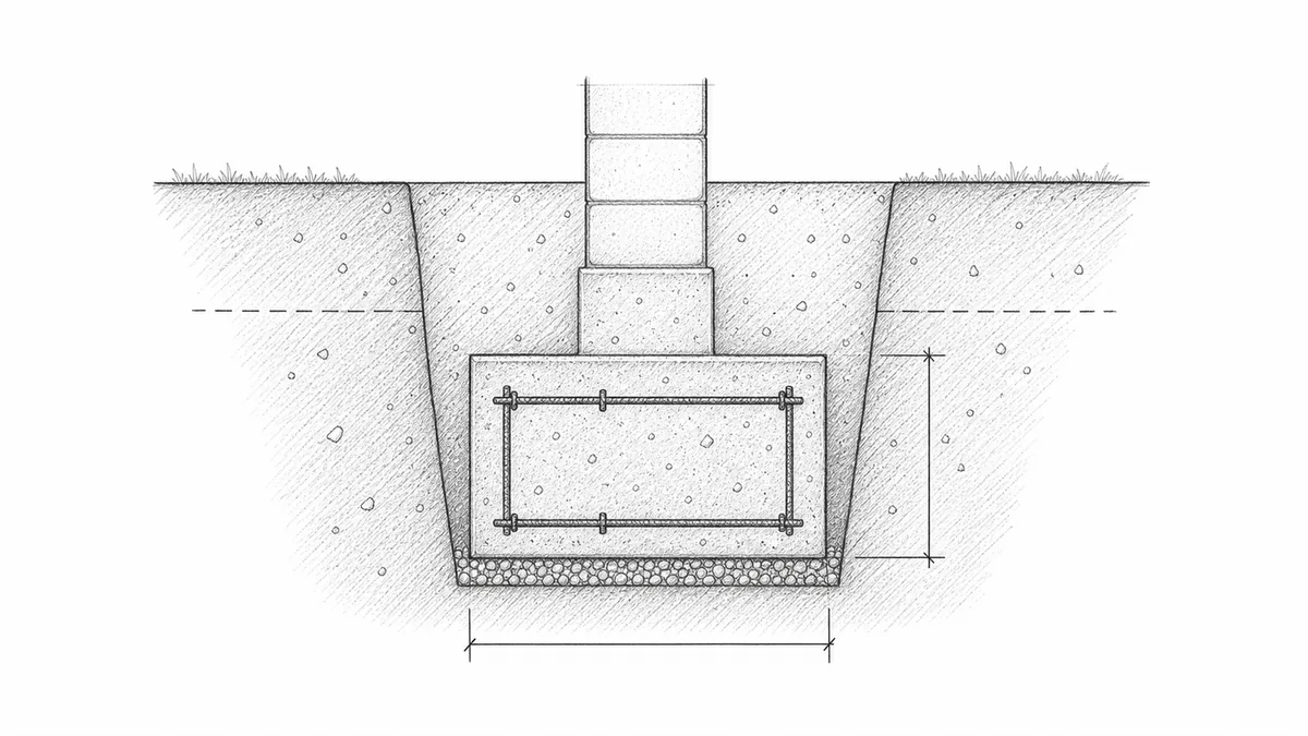
A strip footing is a rectangular prism when its cross-section stays constant. Enter the specified concrete width and depth, not automatically the full excavation width. If an earth trench forms the concrete directly, actual trench overbreak may increase volume and waste.
Split stepped footings, widened pads, intersections, changes in width, and grade beams into separate sections. Add each section once and check intersections so overlapping volumes are not counted twice.
Footing size comes from loads and bearing
The calculator does not determine required width or depth. Those dimensions depend on supported loads, soil bearing, wall thickness, eccentricity, seismic and wind conditions, frost protection, and the adopted code. Structural footings typically require plans or professional review.
The IRC sets the minimum specified compressive strength at 2,500 PSI for most residential footings. In high-seismic zones (Seismic Design Categories D₀, D₁, and D₂) that minimum rises to 3,000 PSI. For reinforcement clear cover, ACI 318 and the IRC require 3 inches on faces cast directly against earth, 2 inches on formed faces exposed to weather for bars #6 and larger, and 1.5 inches for smaller bars.
Frost depth is local
Pour Ready can display a state-level frost-depth approximation after a US ZIP code is entered. That is a planning warning only. State ranges can be broad, border ZIPs can be imperfectly resolved, and the local Authority Having Jurisdiction sets the controlling depth. IRC footing provisions generally require frost-sensitive foundations to bear below local frost depth unless an accepted alternative applies.
Excavation and concrete are different quantities
Working room, form thickness, sloped excavation, trench safety, groundwater, mud removal, and unsuitable soil replacement affect excavation but may not become concrete. Conversely, keyways, pads, thickened intersections, and over-excavated earth forms may add concrete. Keep an excavation sketch and a concrete takeoff sketch as separate documents.
Reinforcement must follow the detail
Longitudinal bars, transverse bars, dowels, laps, hooks, supports, cover, and connections are not determined by the volume formula. Use the structural schedule. Confirm that reinforcing steel and embeds are supported and inspected before placement where required.
Plan placement access
Footings can be difficult to reach with a chute. Confirm truck access, pump needs, crew movement, construction joints, dewatering, and inspection timing. A small calculated yardage can still be a demanding placement if the trench is deep, narrow, or obstructed.
Place concrete in horizontal lifts of 6 to 18 inches and consolidate each lift with an internal vibrator before the next is placed. Penetrate the vibrator at least 6 inches into the previous lift to knit the layers together; visible "pour lines" in the finished footing are cold joints — planes of reduced bond strength. For footings deeper than 30 inches that carry a top layer of reinforcement, re-vibrate the top 12 inches 15 to 45 minutes after initial screeding to close voids caused by bleed water collecting under the top bars.
Footing rules of thumb
A footing's job is to spread the wall load onto soil that can carry it, below the depth where frost can move it. The prescriptive values below come from the IRC and ACI 318; an engineered footing on its own schedule always overrides them.
| Parameter | Typical value | Source / note |
|---|---|---|
| Minimum width | 12 in | IRC R403; wider for soft soil or heavy loads. |
| Minimum thickness | 6 in | Projection each side ≥ 2 in, not more than the thickness. |
| Bottom elevation | Below frost line | Often 42–48 in in cold climates; AHJ governs. |
| Minimum strength | 2,500 PSI | 3,000 PSI in Seismic Design Categories D₀–D₂. |
| Cover, cast against earth | 3 in | ACI 318 / IRC R403.1.3.5.3. |
| Cover, formed and exposed | 2 in (#6+) / 1½ in (#5−) | Removable forms exposed to weather. |
Step by step: placing a strip footing
The yardage is small but the placement can be demanding. This sequence follows the Caltrans RCM and IRC footing provisions.
- Lay out and excavate to bearing. Cut the trench to the specified width and carry the bottom to firm, undisturbed (or properly compacted) soil below the local frost line. Do not bear on frozen or organic soil.
- Verify bearing and remove water. Proof-roll or probe the subgrade for soft spots, and sump out any standing water so it cannot dilute the paste or segregate the aggregate as concrete arrives.
- Place reinforcement on dobies. Set longitudinal bars, dowels, and any transverse steel on chairs or precast dobies that hold 3 inches of cover against earth, and tie laps and corners per the schedule.
- Form the key and exposed faces. Set a keyway for the wall above and brace any formed faces against deflection from concrete pressure.
- Place in horizontal lifts. Deposit concrete in 6 to 20-inch lifts and consolidate each with an internal vibrator for 5 to 15 seconds per insertion, penetrating at least 6 inches into the previous lift so the layers knit and no cold joint forms.
- Reconsolidate deep footings. For footings deeper than about 30 inches that carry top reinforcement, re-vibrate the top 12 inches within 15 minutes of screeding to release bleed water trapped under the bars.
- Screed and set anchors. Strike off to the planned elevation, then set ½-inch anchor bolts to at least 7 inches of embedment while the concrete is still plastic where the design calls for them.
- Cure before loading. Keep the footing damp or covered for 7 days and avoid backfilling or loading the wall above until the concrete has gained adequate strength.
Sources and further reading
Use this guide with the Pour Ready methodology page, project foundation drawings, soil information, and your local building department's footing requirements.
- ACI 318 official code page for structural concrete scope and reinforcement boundaries.
- 2021 IRC Chapter 4 Foundations for residential footing and frost-depth context.